
We’ve previously covered some of the best tools for reversing firmware that you should be using, but before we even get to have some reversing fun we have to extract the firmware and data from EEPROM or Flash.
To do any extraction, it helps to have a rough understanding of the product’s circuit board and storage. When we talk about EEPROM and Flash chipsets, we’re talking about discrete external ICs that are on the circuit board.
Memory Types
Just like a PC needs a hard drive to store the operating system and applications, a microcontroller or microprocessor needs somewhere to store their code. For microcontrollers, this is usually (but not always) done internally. The code can be stored in a few types of non-volatile memory (nonvolatile means that it won’t disappear when you pull the power):
- ROM – this is a fixed memory array inside of a chip that is set by the manufacturer at manufacturing and cannot be modified (unless you use highly custom tools).
- OTP – One-Time programmable memory is designed to be programmed by the product developer once in the factory but can’t be changed later
- Flash Memory – Flash storage uses trapped electrons to store data. Microcontrollers often integrate flash memory internally
Even though ROM is fixed, it may need to be patched with fixes and new features. Take as an example the Infineon (previously Cypress and before that Broadcom) chipsets for Wi-Fi Bluetooth. They have a CPU core for managing the low level radio that runs the Bluetooth stack. That stack is in ROM. But, because there may be bugs, there’s a mechanism to patch the ROM by making it jump to Flash for the patched code (instead of running the original code)
External Flash for Microcontrollers
Integrating Flash memory on the same die as a microcontroller has some downsides, cost being one. If a user needs more memory, you will need to use another chip. More memory takes more space, which can result in a bigger silicon die that may not fit in the package. For these reasons, many microcontrollers use an external memory chip.
An external flash means it’s easier to intercept the communication between processor and flash. External flash chips use SPI or similar.
External Flash for microprocessors
Microprocessors that run Linux (with a few minor exceptions) have external memory (both DRAM and Flash). There is simply not enough space for the gigs of memory you would want in a single die. Some smaller linux devices can integrate 32-64Mbit internally, but they’re the exception.
For these devices, SPI is too slow. Instead, SDIO is used for high speed transfer. SDIO is a high performance interface that’s faster and has multiple bit lines allowing for multi bit transfers.
External EEPROM
EEPROM is a version of EPROM that can be electrically erased and is designed for low speed and small capacities. In the past, these devices needed to be erased with UV light.
Because the technology is somewhat slow, EEPROM chips almost exclusively use the I2C interface. This interface is clocked at either 100kHz, 400kHz or 1MHz. These speeds don’t allow a processor to read code and run from it, which is one reason why EEPROM chips tend to contain configuration information, logging and similar information. Crypto keys and a lot of other data can be found in these chips, which makes it a goldmine.
I2C is an unencrypted interface that is easy to sniff with tools like The Bus Pirate and others. The data in EEPROM chips is also almost always unencrypted. If the EEPROM data was encrypted, the encryption key would need to be present elsewhere to decrypt it. Some processors and microcontrollers do have internal memory that allows for encryption keys to be stored securely.
How to tell if the EEPROM is encrypted? Using binwalk like we explain in this post to look at the entropy. Encrypted regions will show high entropy. To be able to decrypt this data, you’ll need to extract the key from the device which could be difficult.
Here are the signals you need to extract from an EEPROM chip:
| Signal | Description |
| I2C SDA | I2C Data Line |
| I2C SCL | I2C Clock Line |
| GND | Ground |
| VCC | Power |
When you’re interfacing to an EEPROM (or any other chip), it’s important to know what the voltage levels are.
3.3V is the most common voltage in boards, but 1.8V, 1.2V and other voltages are possible. If your equipment uses the wrong voltage, you can damage the chip or your equipment
Before you start anything, measure the voltage VCC with respect to ground using a multimeter. You may need to add level shifters to adjust the voltage.
EEPROM Package and Pinout
One advantage of EEPROM extraction is that the packages for the chips are standard. Most EEPROM devices use SOIC-8 packaging. There are also TSSOP-8 and QFN EEPROMs. EEPROMs are jelly bean parts almost, and product designers tend to go with the cheapest for a given capacity.
EEPROM pinouts are almost always the same, because vendors want to allow manufacturers to switch to their part without redesigning the board. Here’s an example of the pinout of a Microchip 24LC16BT-I/OT EEPROM and an ST Micro EEPROM. Microchip is one of the largest EEPROM vendors.
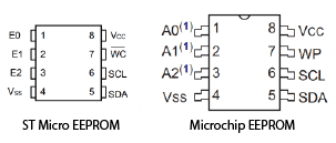
Pins 1 2 and 3 are not connected in either ST’s EEPROM or Microchip’s. VSS is another name for Ground.
WP or WC are the write protect pin that allows or prevents writing to the device. If you’re looking to write to the device, you’re going to need to make that let you write. That depends on the device itself and is the main difference in some chips. We’ll go over dealing with this later
Connecting to EEPROM
When you’re looking at the EEPROM chip on a board, it’s important to find Pin 1. It’s common for vendors to mark pin 1 with a dot or a dimple in the package. It can also be a specific design such as an angled corner. Once you know where Pin 1 is, you know where the rest are by comparing to the package pinout.
There’s quite a few ways to extract the data from the EEPROM
- Desolder EEPROM – desoldering the EEPROM has some risk, but it disconnects it from the rest of the board and let’s you extract without interruption.
- Leads – Single leads like those from the Saleae Logic Analyzer work well, attach relatively quickly. Sometimes the leads lose their grip and can move
- SOIC Chip Clips – They attack directly and reliably in seconds without soldering, but you have to have the right ones and they don’t work with QFN packages
We like using these clips since they work reliably, attach directly to the chip without any soldering.
The benefit of using leads or the chip clips is that you don’t risk desoldering the device. One problem is that you either need to supply power to the device (you can’t read an EEPROM when it has no power) or leave the board you’re using powered. This means that whatever is connected to the EEPROM can issue reads and writes to that device.
This isn’t usually an issue because an EEPROM is read in seconds and EEPROM access typically happens during startup or rarely after boot.
Programming an EEPROM
While reading is pretty straightforward, you may want to program an EEPROM and change some bytes. Maybe clearing an encryption key, or setting a new MAC address, etc. EEPROM chips typically have a write protect pin. Sometimes this pin is left floating or without any write protection. If that’s the case, just leave the pin alone and program the device over I2C.
Write Protect (WP) pins usually are controlled in one of two ways:
- Connected directly to VCC or GND
- Connected to VCC or GND via a resistor
- Controlled by a GPIO pin from another device
For cases 1 and 3, you can desolder the chip or use the lifted leg technique. In this technique you use the soldering iron to heat up the WP pin and use a tweezer to very gently lift it off the pad by sliding the tip of the tweezer between the pin and the pad. The pin will bend upwards. It’s important to bend it just enough or it could break. With the pin floating the write protection of the chip will be disabled (in most cases).
Another option for #3 is to desolder any resistor in series with the signal, but it can be difficult to determine if there’s such a resistor
For case #2, there’s a simpler approach. First, you need to determine if the pin is connected to VSS or VCC through a resistor. You can use a multimeter to measure that pin to the VSS and VCC pins. If the resistance is 1k or above, that’s likely the case. Because there’s a resistor, we can apply voltage to the pin directly that will not harm the system since the resistor will drop the voltage for us (it will waste some power but that’s about it). You can apply VCC or VSS directly.
When you do this, one side of the resistor will be at some level, and the other side will be at the other level. Because you connect the pin to VCC or VSS directly, that resistance is much lower
It’s important to know that the write protect pin may be latched at a particular moment, startup or some other time. If that’s the case, you will want to cycle the power on the chip to ensure the pin state is latched at that moment.
EEPROM Read/Write Protocol
Even though you can just use EEPROM hardware extraction tools to read/write, you want to at least understand at a basic level how the read and writes actually happen.
The best place to read about the details of the protocol is in a datasheet like this one.
To read or write you need to send two things, the command (to let the chip know the operation to perform) and the address. If you’re reading multiple bytes sequentially, then you don’t usually need to provide the address of every byte – the address is incremented internally, so as long as you do an I2C read, you will keep reading every byte.

Reading a byte requires the following process. Note that I2C uses 8-bit operations for data (except START and STOP)
- I2C START is generated by the I2C Master
- Control byte is sent by I2C Master and ACK is received
- The Word address is sent by the I2C Master and ACK is received
- The Control byte is sent again. After the ACK, the EEPROM sends the data at the Word address
- An I2C STOP is sent by the master, ending the read
To read sequentially, the I2C Master needs to send an ACK and continues to run the clock, and the EEPROM clocks out the data.
Writing data to the EEPROM is similar, except that instead of sending a start after the Word address, the master sends 8 bits of data right after the word address. If the master wants to program more than one byte, it can keep sending data bytes and clocking the SCL line.
When you’re using a hardware tool with some utility, these details are hidden from you and the operations are done automatically.
Extracting External Flash
EEPROM is interesting, but the real meat and potatoes of a product tends to be code, and code in external flash is ripe for extraction.
Flash memory comes mostly in two flavors:
- NAND Flash – preferred for Data storage. Higher capacities
- NOR Flash – typically used for code storage and execution as the read speeds are much faster
Because Flash devices are designed for executing code or writing a lot of data, the I2C interface of an EEPROM isn’t enough. Flash devices use SPI interface, either with a single data line or variants such as Dual SPI and Quad SPI. These higher pin SPI have higher throughput.
The standard SPI interface is a relatively straightforward protocol. There’s a data line for each way from the chip (or multiple of them). A master has multiple slave devices. There’s a Chip Select (often called Slave Select) line. The master generates the Clock line that’s also shared to all the slaves.
Even though the Dual I/O read and Quad I/O read help throughput, you don’t necessarily need them when extracting firmware. These features are typically used for Execute in Place (XiP) and running code. When extracting code you’re not under any time constraints, so a bit more time extracting works.
External Flash Package and Pinout
Like EEPROM devices, vendors typically use a standard package and pinout that helps make extracting data from the chip easy

| Pin Name | Description |
| CS | Chip Selects – indicate communications are with this active slave on the SPI bus |
| SI | Slave Data Input |
| SO | Slave Data Output |
| GND | Ground |
| VCC | Power |
| WP | Write protect |
| HOLD | Holds Serial data input |
The devices output the data out on either the rise or fall and then latch the other device’s data on the opposite edge. In most external flash devices, data is latched on the rising clock, which means that on the falling clock edge the data is changed by the master and the slave. SPI is a full duplex protocol, so both device can exchange data at the same time.
eMMC
SD cards and micro SD cards can hold a gigabytes of data in a very small size. This makes sd cards great for root file systems and large storage for embedded Linux.
Adding an SD card to a circuit board means adding an adapter, and also manually inserting a card during manufacturing. This increases the cost. As an alternative, eMMC chips are essentially SD cards that are soldered to the board.
eMMC chips use the same SDIO interface as SD cards, which means that they can be read by SD card readers.
if the Linux device you’re trying to access has an SD card, then it’s as easy as popping it into a reader. But eMMC is soldered directly to the board, making it harder.
One way to deal with extracting firmware from eMMC chips is to remove them with hot air. These chips are usually BGA packages, which are harder to de solder.
You can remove the chip, then solder it to an adapter board that has an SD card form factor. There are sockets as well but they can be expensive.
Desoldering the chip is risky. The heat can damage the chip and recalling BGAs is a pain.
One approach that we’ve found less risky is to solder wires to the SDIO lines. Oftentimes these lines will have series resistors that make the lines accessible. You can then connect an SD card reader with an adapter.
Summary
Extracting firmware and information from devices is crucial to evaluate the security of products and finding vulnerabilities. With the techniques we’ve discussed, you will be able to extract firmware from tough targets.